In addition to retrospective motion correction, I created a training device for kids that teaches them to stay still during an MRI scan. The goal of my training device was to help kids visualize how much they move during a scan. I used a combination of sensors: accelerometer, gyroscope, and magnetometer to detect head motion and orientation. The idea was that kids could put on a headband and see how their heads moved during a simulated scan. If they moved too much, the headband would pause the movie they were watching.

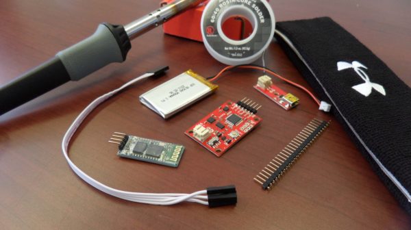
The list of materials I used is:
- Solder
- Soldering Iron
- Needle and thread
- Sweatband
- Small lithium ion battery
- Lithium ion battery charger
- Right angle male headers
- Bluetooth transceiver
- 9 DOF IMU
- 3.3V FTDI cable
- Computer with Arduino and Processing

After I soldered the right angle headers onto the 6 pins of the IMU, I connected the IMU to the computer using the 3.3V FTDI cable to flash the IMU with new firmware. I experimented with two firmwares, FreeIMU and Sparkfun, and my own code. I ended up settling with the Sparkfun code since it had the least drift in yaw values and was less sensitive to calibration errors. I tested this by connecting the IMU to the computer’s serial port using the FTDI cable, making sure to remove the green DTR wire (this wire will auto reset the firmware). This tutorial is helpful on flashing and calibrating the IMU. The only thing I changed in the Sparkfun firmware was the baud rate, which I set at 115200 baud.
To configure the bluetooth transceiver to work with the IMU, I had to set the baud rate of the bluetooth transceiver equal to the value in the IMU firmware. In my case, I used 115200 baud throughout.

To set the baud rate of the bluetooth transceiver, use the FTDI cable to connect the transceiver to the computer. Make sure you connect the right wires to the bluetooth transceiver. Pull the wires out of the connector in the FTDI cable and connect them to their respective headers on the bluetooth transceiver. Once connected, use a serial monitor to program the transceiver. This tutorial is helpful and lists the different AT commands.

Now with the IMU and bluetooth transceiver flashed and programmed, you can connect all the parts: battery, IMU, and bluetooth transceiver. Make sure you connect RX on the bluetooth transciever to TX on the IMU and vice versa.

Once you’ve connected everything, you’re ready to put the parts in a headband. I stress relieved all the electrical connections with electrical tape. Then you open up the headband with scissors and sew all the parts onto the inside of the headband.

To use the headband, just power on the headband and pair it with the computer over bluetooth. Once connected, programs can read the serial data from the IMU wirelessly. I used a sketch in Processing (Java) using the Vitamin library to render a 3D model of Shrek that mimics the movements of the headband. Additionally, if there is too much movement, an instance of the java.awt.Robot class “presses” the spacebar to pause/play a movie.